Test 20: Resistance to hydrolysis and to transformer oil
1 General
This test is applicable to enamelled wire.
Resistance to hydrolysis is expressed by appearance and adherence after exposure of the specimens to transformer oil in the presence of water under pressure and at elevated temperature.
Resistance to transformer oil is expressed by breakdown voltage and flexibility after exposure of the specimens to transformer oil under pressure and at elevated temperature.
NOTE The water can affect the coating by hydrolytic degradation and/or by absorption. If only absorption has occurred, drying the specimen at 1 25 °C ± 3 °C for 30 min prior to the breakdown voltage test will produce a recovery of the specimen. Wire with a nominal conductor diameter between 0,800 mm and 1 ,500 mm has been
generally found convenient to handle and to test.
2 Round wire
2.1 Equipment
The following equipment shall be used:
• two glass tubes of 25 mm diameter and 300 mm length capable of being sealed;
• stainless steel pressure vessel of 400 ml to 500 ml volume with a pressure capacity of 6 × 1 0 6 Pa, preferably of unwelded construction and provided with a controlled heating system;
• transformer oil according to IEC 60296(IEC 60296:2012 is applicable to specifications and test methods for unused mineral insulating oils. It applies to oil intended for use in transformers, switchgear and similar electrical equipment in which oil is required for insulation and heat transfer. );
• paper according to IEC 60554-1 , type 1(Specification for cellulosic papers for electrical purposes. Gives definitions and general requirements, including a designation system and lists of thicknesses. ) .
2.2 Specimens
The following specimens shall be prepared:
• 12 straight pieces of wire with a length of approximately two-thirds of the internal height of pressure vessel;
• 10 twisted pair specimens prepared in accordance with IEC 60851 -5:2008 (A straight piece of wire, approximately 400 mm in length, with the insulation removed at both ends, shall be twisted back on itself for a distance of (125 ± 5) mm on the twisting device.) for nominal conductor diameter up to and including 2,500 mm or 10 straight specimens tested in accordance with IEC 60851 -5:2008(The specimen shall be placed in the container and shall be surrounded by shot at least 5 mm between the specimen and the inner walls of the container. The ends of the specimen shall be sufficiently long to avoid flashover. The shot shall be poured gently into a container until the specimen is covered by shot at a depth of 90 mm. The metal shot shall be not more than 2 mm in diameter; balls of stainless steel, nickel or nickel-plated iron have been found suitable. The shot shall be cleaned periodically with a suitable solvent (for example, 1,1,1-richloroethane).) for nominal conductor diameter over 2,500 mm;
• 3 mandrel-wound specimens prepared in accordance with IEC 60851 -3:2009 (A straight piece of wire shall be wound for 10 continuous and adjacent turns around a polished mandrel of the diameter given in the relevant standard. The mandrel shall be rotated with a rate of 1 r/s to 3 r/s with a tension applied to the wire that is just sufficient to keep it in contact with the mandrel. Elongating or twisting the wire shall be avoided. ) for nominal conductor diameter up to and including 1 ,600 mm or 3 straight specimens tested in accordance with IEC 60851 -3:2009 (A straight piece of wire shall be elongated according to standard to the percentage specified in the relevant standard. After elongation, the specimen shall be examined for cracks or loss of adhesion with normal vision or with a magnification of up to six times.) for a nominal conductor diameter over 1 ,600 mm.
2.3 Procedure
2.3.1 Resistance to hydrolysis
Six straight pieces of wire prepared according to 2.2 are placed in the pressure vessel together with a quantity of de-aerated dry transformer oil sufficient to occupy (52,5 ± 2,5) % of the volume of the pressure vessel. The pressure vessel shall be sealed and heated to (1 50 ± 3) °C for (24 ± 1 ) h, after which it is allowed to cool to room temperature before opening. The specimens shall be examined with normal vision. The test shall be repeated with a quantity of water equal to (0,3 ± 0,1 ) % of the volume of oil used being added to the pressure vessel. One test shall be made. Any changes in appearance and adherence shall be reported.
2.3.2 Resistance to transformer oil
Depending on the diameter and according to 2.2, the pressure vessel shall contain 10 twisted pair or straight specimens, three mandrel-wound or straight specimens and extra pieces of wire to arrive at the volume of coating specified in Table 2.
NOTE The total mass of wire in grams to provide the required volume of enamel can be calculated approximately
by:
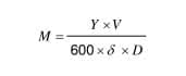
Where V is the volume of the pressure vessel in millilitres;
Y is the mass of 1 m of wire in grams;
δ is the increase in diameter due to the coating in millimetres;
D is the overall diameter of the wire in millimetres.
The pressure vessel shall be charged in accordance with the components and quantities specified in Table 2. Immediately prior to their addition, the oil and paper shall be dried and the oil de-aerated at a pressure of 2 kPa for (1 6 ± 1 ) h at (90 ± 3) °C or for (4 ± 0,30) h at
(1 05 ± 3) °C.
Table 2 – Volume of components
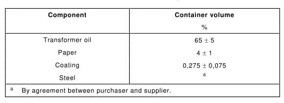
The sealed pressure vessel shall be heated to the class temperature of the wire ±3 °C, or to (1 50 ± 3) °C, if class temperature is higher than 1 50 °C, and maintained for (1 000 ± 1 0) h. The pressure vessel shall then be allowed to cool to room temperature, discharged and opened. Five of the 1 0 specimens shall be tested at (1 05 ± 3) °C for breakdown voltage with the specimens in air in accordance with either 4.4.2 or 4.5.2 of IEC 60851 -5:2008, depending on the conductor diameter. The remaining five of the 1 0 specimens shall be dried at (1 25 ± 3) °C for (30 ± 5) min, allowed to cool to room temperature and then tested at (1 05 ± 3) °C for breakdown voltage in air in accordance with either 4.4.2 or 4.5.2 of IEC 60851 -5:2008, depending on the conductor diameter.
The three specimens shall be examined for cracks according to either 5.1 .1 .1 or 5.2 of IEC 60851 -3:2009, depending on the conductor diameter. One test shall be made. The individual values of breakdown voltage and any cracks shall be reported.
3 Rectangular wire
3.1 Equipment
Equipment according to 2.1 shall be used.
3.2 Specimens
The following specimens shall be prepared:
• 1 0 straight pieces of wire with a length of approximately two-thirds of the internal height of pressure vessel;
• four U-shaped specimens prepared in accordance with 4.7.1 of IEC 60851 -5:2008;
• two mandrel bent specimens prepared in accordance with 5.1 .2 of IEC 60851 -3:2009.
3.3 Procedure
3.3.1 Resistance to hydrolysis
Each of the tubes shall be charged with five straight pieces of wire according to 3.2 and 80 ml de-aerated dry transformer oil. To one of the tubes, (0,24 ± 0,01 ) ml of distilled water shall be added. The two tubes shall be sealed and placed in an oven for 24 h at (1 50 ± 3) °C.
The tubes shall then be removed from the oven, and then allowed to cool down to room temperature and opened. The specimens shall be examined with normal vision.
One test shall be made. Any changes in appearance and adherence shall be reported.
3.3.2 Resistance to transformer oil
The pressure vessel shall contain four U-shaped specimens, two mandrel bent specimens and
extra pieces of wire to arrive at the volume of coating specified in Table 2.
NOTE The total mass of wire in grams to provide the required volume of enamel can be calculated approximately
by:
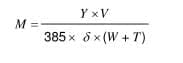
where
V is the volume of the pressure vessel in millilitres;
Y is the mass of 1 m of wire in grams;
δ is the increase in thickness due to the coating in millimetres;
W is the overall width of the wire in millimetres;
T is the overall thickness of the wire in millimetres.
The pressure vessel shall then be charged, in accordance with the quantities specified in
Table 2, with oil and paper which shall have been dried separately immediately prior to addition at a pressure of maximum 2 kPa for (1 6 ± 1 ) h at (90 ± 3) °C or for (4 ± 0,1 ) h at (1 05 ± 3) °C. The sealed pressure vessel shall be heated to the class temperature of the wire
±3 °C, or to (1 50 ± 3) °C if class temperature is higher than 1 50 °C, and maintained for (1 000 ± 1 0) h. The pressure vessel shall then be allowed to cool to room temperature, discharged and opened. Two of the U-shaped specimens shall be tested at (1 05 ± 3) °C for breakdown voltage in air in accordance with 4.7.2 of IEC 60851 -5:2008. The remaining two of the U-shaped specimens shall be dried at (1 25 ± 3) °C for (30 ± 5) min, allowed to cool to room temperature and then tested at (1 05 ± 3) °C for breakdown voltage in air according to 4.7.2 of IEC 60851 -5:2008. The mandrel-bent specimens shall be examined for cracks according to 5.1 .2 of
IEC 60851 -3:2009.
One test shall be made. The individual values of breakdown voltage and any cracks shall be reported.
Annex A
(informative)
Alternative refrigerants to monochlorodifluoromethane Table A.1 provides a list of alternative refrigerants to onochlorodifluoromethane (R 22) that have been found through investigation to be suitable for use in Test 16.
For safety purposes and for their proper application during testing, observation of critical data in this table is recommended.
Table A.1 – Alternative refrigerants to R 22