Common Faults and Diagnosis Techniques of Oil-immersed Distribution Transformer
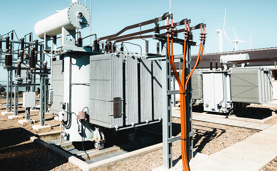
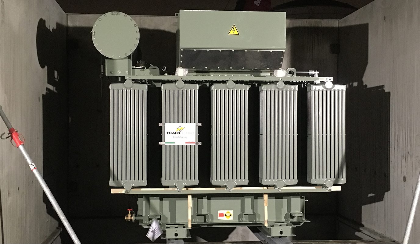
Transformer is one of the most important electrical equipment in the power system, it can change the voltage from low to high or from high to low. Oil-immersed distribution transformer is the most common type of transformer, and it is also the most used transformer. Once an abnormal situation occurs during the operation of the transformer, it will affect the normal operation of the system and the normal power supply to users, and even cause large-scale power outages. This paper introduces the common defects and faults of oil-immersed distribution transformers, analyzes the harm of these faults to the transformer, and summarizes the methods to eliminate the faults.

1. Common faults and their diagnostic measures
1.1 Transformer oil leakage
1.1.1 The oil seepage from the weld seam of the fuel tank is solid.
For oil leakage at plane joints, welding can be performed directly. For oil leakage at corners and reinforcement joints, it is often impossible to find the leakage point, or leakage occurs again due to internal stress after repair welding. For such infiltration points, iron plates can be added for repair welding. At the junction of two sides, the iron plate can be cut into a spindle shape for repair welding; at the junction of three sides, the iron plate can be cut into triangles for repair welding according to the actual position.
1.1.2 Casing oil leakage
For casing oil leakage, it is generally caused by casing rupture or cracks, improper installation or aging of gaskets, and loosening of casing compression screws. If the accessories must be replaced in the first two cases, if the screws are loose, re-tighten the screws.
1.2 Core multi-point grounding
1.2.1 DC current impulse method
Remove the grounding wire of the transformer core, apply a DC voltage between the transformer core and the oil tank for short-term high-current impact, impact 3 to 5 times, and often burn off the redundant grounding point of the core, which can effectively eliminate the multi-point grounding of the core. Effect.
1.2.2 Unpacking inspection
If the positioning pin on the box cover is not turned over or removed after installation, resulting in multi-point grounding, the positioning pin should be turned over or removed. If the insulating cardboard between the clamp pad and the iron yoke falls off or is damaged, it should be replaced with a new cardboard of a certain thickness according to the requirements of the insulation code. Because the clamp limb plate is too close to the iron core, so that the lifted lamination collides with it, the clamp limb plate and the lifted laminate should be adjusted so that the distance between them meets the insulation gap standard. Remove metal foreign matter, metal particles and impurities in the oil, remove oil sludge in various parts of the oil tank, and if possible, vacuum-dry the transformer oil to remove water.
1.3 Connector overheating
1.3.1 Conductive Rod Terminal Connection
The lead-out terminals of the transformer are made of copper, and the aluminum conductor cannot be connected to the copper terminal with bolts in outdoor and humid places. When water containing dissolved salts, that is, electrolyte solution, penetrates between the contact surfaces of copper and aluminum, an electrolytic reaction will occur under the action of the galvanic coupling, and the aluminum will be strongly galvanically corroded. As a result, the contacts are destroyed quickly, so that heat is generated and even a serious accident may be caused. In order to prevent this phenomenon, it is recommended not to use copper-aluminum connection.
2. Transformer temperature monitoring
2.1 Infrared temperature measurement technology
Infrared thermal imaging technology uses an infrared detector to receive the infrared radiation signal of the target to be measured, and after amplification processing, converts it into a standard video signal, and then displays the infrared thermal image on a TV screen or monitor. Poor contact of transformer lead wires, overload operation, etc. will cause partial overheating of the conductive circuit, and multi-point grounding of the iron core will also cause overheating of the iron core.
2.2 Oil surface temperature indication
The oil surface temperature indicator is used to monitor the temperature of the oil surface of the transformer, give an alarm when the limit is exceeded, and start a protection trip when necessary.
3. Conclusion
In the 21st century, various aspects rely on the power system and the development of the power system on a larger scale. The fault diagnosis and condition-based maintenance of power transformers, as a powerful measure to realize the system transformation of my country’s power system and improve the scientific management level of power equipment, is the future. The direction of efforts and development in electricity production.

