Continuously
Transposed Cable

Used for medium and ultra-high power transformers in electrical equipment, Transmission and distribution centers, Military and defense etc.
  • Global delivery as fast as 15 days
  • Has factory stock, free sample
  • Paper CTC Conductor, CTC wire without paper
  • wooden spool or Metal reel
  • About 2500kg - 3500kg per roll
  • ISO 9001:2020, UL certificate
Home » Continuously Transposed Cable

What is Continuously Transposed Cable?

Continuously Transposed Cable (CTC) is a type of electrical conductor used primarily in the windings of large power transformers and reactors. It is designed to reduce losses and improve the efficiency and performance of these electrical devices.

Key Features:

  1. Structure:
    • CTC consists of multiple thin, rectangular, and insulated copper or aluminum strands that are transposed (twisted and swapped) along their length.
    • The strands are typically arranged in a rectangular stack, which allows for compact and efficient use of space.
  2. Transposition:
    • The strands are regularly transposed (swapped in a precise pattern) to equalize the electrical and magnetic environments experienced by each strand. This helps in minimizing eddy current losses and circulating currents.
  3. Insulation:
    • Each strand is individually insulated, usually with a thin film of enamel or another insulating material. The overall bundle is then insulated as a whole to prevent short circuits between strands and layers.

transposed cable aluminum
ctc wire

Continuously Transposed Cable - benefits

  • Reduced Eddy Current Losses:
  • Improved Efficiency:
    • By reducing eddy current losses and circulating currents, CTC improves the overall efficiency of transformers and reactors.
  • Enhanced Cooling:
    • The design allows for better cooling of the windings, as the multiple strands and their arrangement facilitate heat dissipation.
  • High Mechanical Stability:
    • The transposition and bundling of strands provide a high degree of mechanical stability, which is crucial for withstanding the mechanical stresses encountered during operation and short-circuit conditions.

Continuously Transposed Cable

Continuously Transposed Conductor Specifications

Transposition number 5 – 80 (odd or even optional)
Maximum dimension height 120 mm, width 26 mm (tolerance ± 0.05 mm)
Single conductor size thickness a: 0.90 – 3.15 mm, width B: 2.50 – 13.00 mm (tolerance ± 0.01 mm)
The recommended width thickness ratio of a single conductor 2.0 < B / a < 9.0
The recommended coating thickness of enameled wire 0.08-0.12mm
The thickness of adhesive layer 0.03-0.05mm
Continuously Transposed Cable

Applications:

Power Transformers: CTC is widely used in the windings of power transformers, especially in large, high-voltage transformers where efficiency and reliability are critical.
Reactors: In electrical reactors, which are used to control current and voltage in power systems, CTC helps in managing the losses and improving performance.
Large Inductors: Used in large inductors where similar benefits of reduced losses and improved cooling are desired.

How to produce the CTC?

ctc producing

Materials and Preparation

  1. Selection of Conductor Material:
    • Copper or aluminum strips are typically used for CTC due to their excellent electrical conductivity.
    • The strips are usually rectangular in cross-section to maximize packing density and minimize losses.
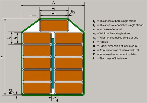
  2. Insulation:
    • Each individual strand is coated with an insulating layer, usually a thin film of enamel or another insulating material.

Manufacturing Process

  1. Strand Preparation:
    • The conductor strips are cut to the desired length and dimensions.
    • The strips are then coated with the insulating material if they are not pre-insulated.
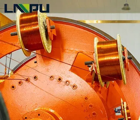
  2. Stranding and Stacking:
    • The insulated strands are arranged in a specific pattern and stacked to form a bundle.
    • The arrangement ensures that each strand is in the correct position for subsequent transposition.
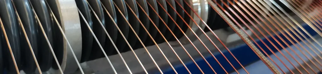
  3. Transposition:
    • The strands are continuously transposed along the length of the cable. This involves twisting and swapping the positions of the strands in a precise and regular pattern.
    • This transposition ensures that each strand experiences similar electrical and magnetic environments, reducing losses due to eddy currents and circulating currents.
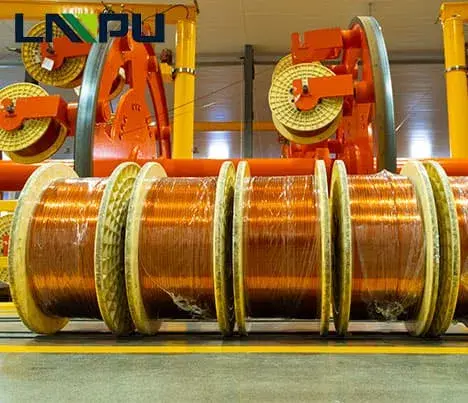
  4. Binding and Wrapping:
    • The transposed bundle of strands is bound together using a suitable binding material.
    • An additional layer of insulation is often applied to the entire bundle to provide mechanical protection and electrical isolation from other components.
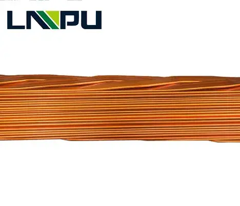
  5. Forming and Shaping:
    • The CTC is shaped into the desired form, which could be a rectangular or oval cross-section, depending on the application.
    • This shaping process ensures that the CTC fits properly into the transformer or reactor windings.

Quality Control and Testing

  1. Electrical Testing:
    • The completed CTC is subjected to various electrical tests to ensure it meets the required conductivity and insulation specifications.
    • Tests include measuring resistance, insulation integrity, and checking for continuity.
  2. Mechanical Testing:
    • Mechanical properties such as flexibility, tensile strength, and resistance to mechanical stresses are tested.
    • Ensuring that the CTC can withstand the mechanical demands of the application is crucial.
  3. Thermal Testing:
    • Thermal performance is evaluated to ensure the CTC can operate within the desired temperature range without degradation.

Final Assembly and Packaging

  1. Final Inspection:
    • A thorough inspection is conducted to check for any manufacturing defects or inconsistencies.
    • This includes visual inspections and verification of all test results.
  2. Packaging:
    • The finished CTC is carefully packaged to prevent damage during transportation.
    • Appropriate labeling is applied to ensure traceability and proper handling instructions.